• Welcome to BirdForum, the internet's largest birding community with thousands of members from all over the world. The forums are dedicated to wild birds, birding, binoculars and equipment and all that goes with it.

    Please register for an account to take part in the discussions in the forum, post your pictures in the gallery and more.
ZEISS DTI thermal imaging cameras. For more discoveries at night, and during the day.

Red Dot Sights (Reflex Sights) on Spotting Scopes (1 Viewer)

Red-dot mounting collar for Kowa 883

Here are some more detailed photos of the red-dot sight mounting. All parts were made from a plate of aluminum alloy (AlMg4,5Mn), thickness 10mm. Planned with CAD, machined with a CNC-mill.

The sight itself can be mounted and detached, all I need is a 3mm hex wrench.
Maybe I'll replace the hex socket screws by knobs one day to be more independent in the fields..
 

Attachments

  • 72B9BDB3-E7B4-4692-9C7F-520E690B6873.jpeg
    72B9BDB3-E7B4-4692-9C7F-520E690B6873.jpeg
    258.2 KB · Views: 225
  • 7824A7EC-3010-45EC-8FF2-D5DAF435459F.jpeg
    7824A7EC-3010-45EC-8FF2-D5DAF435459F.jpeg
    272.9 KB · Views: 195
  • F2AD4893-15E7-4AB3-8D21-99908B839A7C.jpeg
    F2AD4893-15E7-4AB3-8D21-99908B839A7C.jpeg
    269.2 KB · Views: 171
  • 5FD119C2-2FAC-4863-B282-C90647AB1AFA.jpeg
    5FD119C2-2FAC-4863-B282-C90647AB1AFA.jpeg
    280.1 KB · Views: 177
  • 0D43B813-B53C-4641-B887-91A7CE0A5216.jpeg
    0D43B813-B53C-4641-B887-91A7CE0A5216.jpeg
    250.8 KB · Views: 194
Collar mounted on the scope..
 

Attachments

  • 4F64CB20-B359-4A7B-84D5-B8A048FF0BF2.jpeg
    4F64CB20-B359-4A7B-84D5-B8A048FF0BF2.jpeg
    328.4 KB · Views: 234
  • BE8598D6-8BE9-4BDE-BA25-485E81B66B54.jpeg
    BE8598D6-8BE9-4BDE-BA25-485E81B66B54.jpeg
    331.3 KB · Views: 181
Moin!

Here are some more detailed photos of the red-dot sight mounting. All parts were made from a plate of aluminum alloy (AlMg4,5Mn), thickness 10mm. Planned with CAD, machined with a CNC-mill.

Beautiful! Looks like the work of a true professional! :)

Since you can remove the sight holding arm without having to remove the entire mounting, I guess that's the way you achive repeatable alignment?

What's the reason you included an indditional elevation adjustment in the body ... just to make make sure you wouldn't exceed the sight's fine adjustment range?

Which CAD program do you use, by the way? I'm using FreeCAD, which in some respects is great, but in others it's not (yet), which can be quite frustrating at times.

Regards,

Henning
 
Mainly with a tripod, but I will lean it on anything handy.

Regards

Malky


Cool - equipped with a reflex sight right off the shelf! Do you use it offhand or from a monpod/tripod?

Regards,

Henning[/quote]
 
Moin!
Since you can remove the sight holding arm without having to remove the entire mounting, I guess that's the way you achive repeatable alignment?
That's the point. I can either remove the red dot sight itself or detach it with the aluminum holder, just leaving the collar mounted on the scope. The alignment keeps mostly fine.

What's the reason you included an indditional elevation adjustment in the body ... just to make make sure you wouldn't exceed the sight's fine adjustment range?
The intermediate piece is just for additional height adjustments in case I'll need it. I was afraid the range of the red-dot sight's internal alignment might not be wide enough to compensate design faults... I didn't trust in my measuring skills too much :-D

Which CAD program do you use, by the way? I'm using FreeCAD, which in some respects is great, but in others it's not (yet), which can be quite frustrating at times.
I'm using Draftsight for 3D needs and a scrapbook with pen for first drawings... I like the old-fashioned way
 
Last edited:
Moin!

Here's my new design for a sight mounting. I went for an offset mount because it gets the sight line a bit lower, which helps when using the scope in hides with narrow viewing slits.

It's also nice because even if my scope is set up too high for my girlfriend to use it, she can still look through the sight so she knows where to point her own scope :)

Kowa NATO.jpg

right, the threaded ring cover is used as a nut to hold down the aluminum collar. The inner diameter of the mounting collar is just 2/10mm larger than the scopes accessory thread.

I have built the model with a 55 mm inner diameter. Does that sound right to you? My 3D printing provider does not provide 0.1 mm accuracy, so I'm a bit cautious.

To mount it, you have to detach the eyepeace and cover ring, place the collar, screw down the ring and attach the eyepiece back.

Looks like you have 2 mm of thickness in the collar below the ring? This looks a bit tricky as the thread doesn't have many turns and I'll be printing in plastic.

The intermediate piece is just for additional height adjustments in case I'll need it. I was afraid the range of the red-dot sight's internal alignment might not be wide enough to compensate design faults... I didn't trust in my measuring skills too much :-D

Hehe, same thing here :) I measured an angle of close to 50 degrees, but I guess I'll have to make my mounting adjustable too.

I'm using Draftsight for 3D needs and a scrapbook with pen for first drawings... I like the old-fashioned way

Looked it up, and the description is promising. It seems to be marketed as a 3D tool, though? Interesting it's a member of the CATIA family, quite a few of my friends here in Hamburg work with that.

Regards,

Henning
 
Moin!
Moin!

Here's my new design for a sight mounting. I went for an offset mount because it gets the sight line a bit lower, which helps when using the scope in hides with narrow viewing slits.
Sounds clever to meet these special needs! The angle of the mount seems to be fixed?
I have built the model with a 55 mm inner diameter. Does that sound right to you? My 3D printing provider does not provide 0.1 mm accuracy, so I'm a bit cautious.
I'm going to check my CAD-drawings and let u know..
Looks like you have 2 mm of thickness in the collar below the ring? This looks a bit tricky as the thread doesn't have many turns and I'll be printing in plastic

The thickness of the inner collar is 1.5mm, the outer height is 3mm (oops.. maybe it's just 2.5mm, have to check that) around. The front part of the collar is 10mm. This makes the whole collar quite sturdy.

The outer collar's height should not exceed too much height, as you need enough space to place your fingers to tighten the threadened cover ring. This ring is tapered, so its not easy to apply much force. I'm thinking about turning a new ring with a more finger friendly shape to tighten it with some more force if necessary.

Hehe, same thing here :) I measured an angle of close to 50 degrees, but I guess I'll have to make my mounting adjustable too.

The angle between the optical axis of the lens and the eyepiece is 45°.
I also was not sure about that (measured 46°), but the real life test and measuring between the attached mounting plate and the collar showed exactly 45° then.
Looked it up, and the description is promising. It seems to be marketed as a 3D tool, though? Interesting it's a member of the CATIA family, quite a few of my friends here in Hamburg work with that.

Regards,

Henning

Cheers :)
 
Last edited:
Moin!

did You think about a turnable mounting plate? Should be easy by printing a collar with a socket at it's side (with just a hole in it) and a 360° turnable plate, locked by a screw.

As it's made from plastic (PLA, ABS?), the screw will cut it's thread by itself.

Cheers!
 

Attachments

  • FE4EA15E-8746-405E-BE9D-C8D8CBEEC056.jpeg
    FE4EA15E-8746-405E-BE9D-C8D8CBEEC056.jpeg
    352.8 KB · Views: 202
Moin!

did You think about a turnable mounting plate? Should be easy by printing a collar with a socket at it's side (with just a hole in it) and a 360° turnable plate, locked by a screw.

That's about what I had in mind. I was even thinking of using a standard 1/4" tripod screw for this to make it "even more standard".

Here's a NATO rail I made for mounting on a telephoto lens collar (so that when it's turned up, you can mount a sight):

NATO Lens Collar.jpg

On the other hand, I don't like really like the tripod screws since they have so wide slits no screwdriver really fits, and you have to use a coin. If the screw head is recessed, as in the NATO rail, a round coin will not even reach the screw.

My hope is to get the angle right and end up with a fixed part. That will eliminate one possible source of mis-adjustment.

It will be short enough to leave it on at all times (I hope), and I'll only remove the sight itself.

Since my sight needs an extra adapter, NATO-to-11-mm-dovetail, and this adapter has a single screw with a big knob, that will be quick. Good thing I bought the wrong kind of sight ;-)

Dovetail Sight on NATO Adapter.jpg

The outer collar's height should not exceed too much height, as you need enough space to place your fingers to tighten the threadened cover ring. This ring is tapered, so its not easy to apply much force. I'm thinking about turning a new ring with a more finger friendly shape to tighten it with some more force if necessary.

Tha
The outer collar's height should not exceed too much height, as you need enough space to place your fingers to tighten the threadened cover ring. This ring is tapered, so its not easy to apply much force. I'm thinking about turning a new ring with a more finger friendly shape to tighten it with some more force if necessary.

Agreed, when I was looking at my design, I thought "I probably made the walls too high". Of course, working in plastic (laser-sintered nylon powder), I thought a bit more material wouldn't hurt. Great idea to turn a new ring, I'd imagine it will help a lot to keep alignment intact!

(Do you do the CNC stuff yourself, or do you have it done at a shop? I'd imagine the latter option would be quite expensive. Something like my cheapo plastic version might come at 20 EUR, so it won't cost me an arm and a leg to replace it if I get the angle wrong.)

Tschüs!

Henning
 
Moin!
Moin!

(...) That's about what I had in mind. I was even thinking of using a standard 1/4" tripod screw for this to make it "even more standard".

Here's a NATO rail I made for mounting on a telephoto lens collar (so that when it's turned up, you can mount a sight):

View attachment 650924

(...)
(Do you do the CNC stuff yourself, or do you have it done at a shop? I'd imagine the latter option would be quite expensive. Something like my cheapo plastic version might come at 20 EUR, so it won't cost me an arm and a leg to replace it if I get the angle wrong.)

That really looks great, how sturdy are these nylon printed parts? I got no experience in 3D-printing and it's about time, I guess.

And yes, I do that metal stuff by myself, using my 3-axis CNC mill and a small conventional turning lathe. My workshop still lacks a 3D printer so far.

Tschüssken :)
 
Moin!

That really looks great, how sturdy are these nylon printed parts? I got no experience in 3D-printing and it's about time, I guess.

And yes, I do that metal stuff by myself, using my 3-axis CNC mill and a small conventional turning lathe. My workshop still lacks a 3D printer so far.

So far, I've not made any parts that would really load up stress on the material.

I've mostly been using 3 mm wall thickness, which felt really strong.
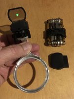
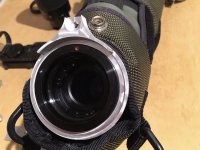
In this picture ...

Sight and Mountings.JPG

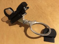
... the clamp of the big sight mounting for the Kowa has 3 mm thickness. You can easily bend the ends together without much force, but the material springs back when you release it.

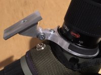
The small white rail (which goes on a hotshoe) experimentally took a 450 g target scope without sagging. That was just for fun, normally it only takes the red dot sight, but I was pleased it held up so well.

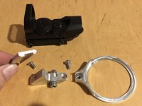
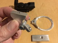
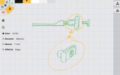
Thin stuff like the base ring of the accessory thread sight mounting is a bit more of a concern, thus my attempt to bring some load on higher walls (which get in the way of screwing on the cover ring).

The advantage of 3D printing is that you can do arbitrary shapes, and it's all produced in one go. I'd guess CNC-milling all the slots in the rail would have been quite time-consuming ... the 3D printer just adds stuff whereever it's needed, regardless of complexity.

I don't actually have a 3D printer, but use online services for printing. The black parts in the picture are from shapeways.com, the white rail is from meltwerk.com. Meltwerk often is cheaper, but the prints from Shapeways seem to be a bit more refined. Shapeways also offers printing in other materials, even steel, but that tends to be more expensive.

(I just checked a somewhat slimmer version of the accessory-thread sight adapter, and Shapeways say in steel it's just over 50 EUR.)

The laser-sintered stuff you get from the service providers is pretty homogenous. The exact printing process seems to require a lot more attention if you're using a typical consumer 3D PLA printer, not only because you have to fiddle with the process parameters until it all works, but also because depending on the intended purpose of the part, you'll want to have the layers oriented in a certain way so they bear the load, or can be printed most accurately, etc.

I don't think a consumer 3D printer can beat a personal CNC mill, but I guess it will be a nice addition since it has a quite different set of strengths :) In fact, I read that some people prefer to buy the CNC mill first, and then use it to build a 3D printer that's way better than what you can buy in the store!

However, I'm sure a CNC mill requires a lot of knowledge about metal working, so I'm not tempted to buy one right away - though looking at your beautiful mounting, I'm almost tempted ;-)

Regards,

Henning
 
Here are some more detailed photos of the red-dot sight mounting. All parts were made from a plate of aluminum alloy (AlMg4,5Mn), thickness 10mm. Planned with CAD, machined with a CNC-mill.

The sight itself can be mounted and detached, all I need is a 3mm hex wrench.
Maybe I'll replace the hex socket screws by knobs one day to be more independent in the fields..

Beautiful craftsmanship Vollmeise :t:

I just wondered if the collar was shaped like a retaining spring washer whether it would be possible to clip it into place almost instantly - I'm not sure how practical this would be, or even which material would be most suitable but the thought of a "snap on" sight mount is quite appealing.

This the kind of shape I mean.

Retaining-Washer-for-Shaft.jpg
 
Hi Torchepot,

I just wondered if the collar was shaped like a retaining spring washer whether it would be possible to clip it into place almost instantly

With plastics that don't damage the thread, that could work. I guess you'd still have to unscrew the cover ring first, and screw it back on after, but you'd have eliminated the need to remove and replace the eyepiece.

For another variant of the "front tube" adapter, I considered a quick release lever. Now I'm wondering if it would be possible to leave of the cover ring and clamp the adapter in place with the quick release, using the threads and the few millimeters of stationary eyepiece above that.

In both cases, the difficulty probably would be to get repeatable alignment. If you leave the collar on the scope, you don't need to realign it if you re-attach the sight-bearer.

Here's the quick-release version of my "front tube" mounting ... I gave up on this when I realized it only works without the stay-on case, and it takes too long to remove the stay-on case on a regular basis:

Kowa NATO Quick Release.jpg

Regards,

Henning
 
A snap on mount sounds cool. Maybe the snap on part shouldn‘t be snapped on the scope‘s thread directly, due to some reasons. First, much force would be necessary not to loose it by accident and second: there would be no way to snap it right without further steps of alignment.

How about an additional plastic collar (with some notches for repeatable alignment), being was placed firm and permanent around the eyepiece thread? A snap on red dot mount could be shaped much more sturdy then and no damage of the thread is possible. Placing a V-shaped notch in the inner top circle position can make it self aligning furthermore. That V-notch then has to fit in a roof-top shaped counterpart, placed in the permanently mounted eyepiece collar for self-alignment.
 
Moin!

How about an additional plastic collar (with some notches for repeatable alignment), being was placed firm and permanent around the eyepiece thread?

Good idea! :) Here's a quick sketch (using OpenSCAD):

Snap-on Base.jpg

The lower ring is screwed on by the cover ring as before. The four posts providet the anchoring points for a quick-release ring. The upper ring has a bigger diameter and only serves to stablize the mounting. Through the holes between the posts, you can screw down the cover ring firmly.

I could also imagine a U-shaped snap on adapter, which each leg snapping on two of the posts. That might eliminate the quick-release without requiring as much bending to open it as with an almost-closed ring.
 
Moin!
Placing the base mount by forcing down the threadened eyepiece ring only doesn’t seem to be the best solution, as my experience with the aluminum collar shows. No matter how much you tighten the cover ring (by your finger‘s force), the collar can be turned by accident anyway.

If the base ring was mounted more like your very first sight clamp (with a back screw to close the clamp), one can mount it directly around the accessory thread, without the cover ring. The plastic clamp won‘t damage the thread and should be more save against rotation by accident. The anchoring points are cool for repeatable alignment, I‘d keep that idea.
 
Last edited:
Moin!

If the base ring was mounted more like your very first sight clamp (with a back screw to close the clamp), one can mount it directly around the accessory thread, without the cover ring. The plastic clamp won‘t damage the thread and should be more save against turnament by accident. The anchoring points are cool for repeatable alignment, I‘d keep that idea.

Thanks for the tip! I'm not sure it will work as the dimensions are so small, but it's worth a try.

Here's another shot of the snap-on adapter. A bit difficult to make proper tangents in OpenSCAD, at least for me, so it's still a bit rough:

New Mount.jpg

Regards,

Henning
 
Warning! This thread is more than 3 years ago old.
It's likely that no further discussion is required, in which case we recommend starting a new thread. If however you feel your response is required you can still do so.

Users who are viewing this thread

Back
Top