• Welcome to BirdForum, the internet's largest birding community with thousands of members from all over the world. The forums are dedicated to wild birds, birding, binoculars and equipment and all that goes with it.

    Please register for an account to take part in the discussions in the forum, post your pictures in the gallery and more.
ZEISS DTI thermal imaging cameras. For more discoveries at night, and during the day.

Distortion in Alpha Binoculars (1 Viewer)

henry link

Well-known member
Last month I photographed the distortion characteristics of four expensive roof prism binoculars: The new "Swarovision" 8.5x42, Nikon 8x42 EDG, Zeiss 4x42 FL and Leica 8x42 Ultravid. I'm just now getting around to making slides that demonstrate the differences among them.

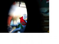
I used two targets that were handy in the store; a round suction cup to show the effect on shapes of angular magnification distortion and and a straight window frame to show the curving of lines caused by the pincushion form of rectilinear distortion used in binoculars. What you can see from the photos is that none of the binoculars is distortion free. In fact that is impossible. If rectilinear distortion is reduced to zero that creates angular magnification distortion. Achieving relative freedom from angular magnification distortion is only possible by the application of pincushion distortion. The problem is similar to what map makers face in trying to produce a flat map of the sphere of the earth.

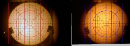
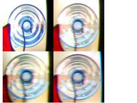
The left slide shows the angular magnification distortion of a circular shape at the edge of the field. Swaro is upper left, Nikon is upper right, Zeiss is lower left and Leica lower right. The Zeiss is the most nearly distortion free which in this case means a perfect circle with the horizontal and vertical diameters equal. The Swaro has the highest angular magnification distortion because it has virtually no pincushion distortion, so the circle appears as if it were seen from an oblique angle. The Leica has a little too much pincushion for exact compensation so that the horizontal diameter of the circle is wider than the vertical diameter, essentially reverse angular magnification distortion.

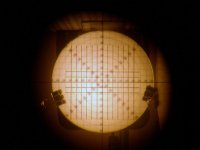
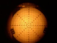
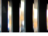
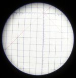
The right slide (Sorry, that slide is in post # 2) shows the rectilinear distortion of the window frame. Swaro is on the far left, then moving right Nikon, Zeiss and Leica. The Swaro has virtually no rectilinear distortion and the Nikon has a very little pincushion. The Zeiss and Leica show increasing amounts of pincushion which is more obvious in viewing through the Leica because its apparent field is smaller.

The designers of these binoculars made different decisions about distortion. The Swarovski designers made an unusual choice of zero pincushion which leads to considerable angular magnification distortion. The Nikon designers applied slight pincushion which leaves a little angular magnification distortion, but doesn't cause lines to curve very much. Zeiss applied more pincushion which mostly correct angular magnification distortion but causes lines to visibly curve and Leica, for reasons I don't understand, applied a little more pincushion than is really needed.
 

Attachments

  • Slide1.jpg
    Slide1.jpg
    86.6 KB · Views: 840
Last edited:
Sorry, I wasn't able to include the window frame slide that shows rectilinear distortion in the first post so here it is.
 

Attachments

  • Slide1.jpg
    Slide1.jpg
    63.4 KB · Views: 700
Thanks Henry, accurate and well presented.

I might offer some guesses as to the curvature choices, only guesses mind you, based on experience with both Zeiss and Leica photogrametry lenses. This is were we measure the angle from two known focal points and measure the angles, horizontally and vertically from the optical axis of each of the two images and project them to intersection at a known 3D point in space. These lenses are designed to, very accurately, reproduce the image angle from the principal point / optical axis. These usually scale accurately for focal length. Binoculars have eyepieces that allow for some correction of the curvature at the expense of other parameters, say astigmatism or other parameter. I suspect that these do not scale for focal length or apparent angle as well as the objective because of the shorter, more divergent factors. This could lead to two different sources, one, the eyepiece was designed for a different configuration and scaled or, two, that the tolerance of the focal length is critical enough to show the error, i.e. magnification times tolerance.

And, then again, the designer might just think more curvature is aesthetically appealing.

I have been doing some experimenting along the same lines and after seeing your examples, I think I will add concentric rings to my test target.

I find it really helps understand some edge problems. Notice the edges of attached. The red grid is computer generated for reference against a constant distance/angular offset.

Best
Ron
 

Attachments

  • Left Field Stop.jpg
    Left Field Stop.jpg
    50.1 KB · Views: 309
  • P7200009.JPG
    P7200009.JPG
    91.5 KB · Views: 289
The problem is similar to what map makers face in trying to produce a flat map of the sphere of the earth.
.

Thanks a lot for the explanation. I am still trying to understand the content of your presentation. But this summary definitely helps a lot for non techy like me.
 
Very nice presentation, Henry.

For others who haven't read the Holger's globe (rolling ball) effect papers try it now and keep Henry's results in mind. As he said some of these decisions seem to be "house style".

Links are over on this thread.

http://www.birdforum.net/showthread.php?t=140202

I must say that Swaros choice for no distortions is an interesting one (almost harking back to Zeiss' old stance). Will it work out for them and their users? The reviews will tell.
 
Very nice presentation, Henry.

For others who haven't read the Holger's globe (rolling ball) effect papers try it now and keep Henry's results in mind. As he said some of these decisions seem to be "house style"..

Kevin,

Those decisions on distortion are definitely made by each manufacturer (at least the ones who make their own product). Optical tastes are different and now we can see it via Henry's nice work. I know it's not a case of "you get what you get"

Just like car styling or any physical product the optical view can be thought of as a tangible "product" of a company where it can evolve through time to be made better yet still keep familiar properties.

Do doubt why hunters and birders have their favorites and why the big 3 have such passionate followers.

Cheers
 
Henry,
Thanks for the photos and comparison of the top binos in existence. No matter what anybody says, you are not an optical lowlife. This is a very interesting subject, and has been discussed enough here that I am actually starting to get it!

Holger Merlitz tells how perfect rectilinearity was the norm until Zeiss changed the rules in 1947, and the world mostly followed (as usual). I suppose this happened with the advent of the need to pan after rapidly moving airplanes, and was reinforced at some point by the popularity of birding, whose flight is often followed by binoculars. Rectilinearity is obviously better if the view is stationary.

But, if you took somebody who had no preconceptions, like 99% of bino users, I mean even the sharp eyed and experienced, even expert ones, and had them follow a flying bird, would pincushion or rolling globe seem more "natural"? Our innocence is kaput, our minds poisoned by knowledge. But I would choose pincushion.
Ron
 
Last edited:
Henry,
Thanks for the photos and comparison of the top binos in existence. No matter what anybody says, you are not an optical lowlife. This is a very interesting subject, and has been discussed enough here that I am actually starting to get it!

Holger Merlitz tells how perfect rectilinearity was the norm until Zeiss changed the rules in 1947, and the world mostly followed (as usual). I suppose this happened with the advent of the need to pan after rapidly moving airplanes, and was reinforced at some point by the popularity of birding, whose flight is often followed by binoculars. Rectilinearity is obviously better if the view is stationary.

But, if you took somebody who had no preconceptions, like 99% of bino users, I mean even the sharp eyed and experienced, even expert ones, and had them follow a flying bird, would pincushion or rolling globe seem more "natural"? Our innocence is kaput, our minds poisoned by knowledge. But I would choose pincushion.
Ron

I would chose the view that looked most like my naked eye view, both stationary and while panning.

I have found that too much pincushion can be as distracting as too much "rolling ball".

When I look at nature, I want it to look "natural," not like a ball or a saddle.

I'll leave the other views to the Riemannians to sort out. :)
 
Thanks guys.

Ron's photos show a way to image distortion by photographing a grid pattern through the binocular backwards so that the full circle of the eyepiece fieldstop can be photographed. It's better than the method I used in the store for showing the full field distortion. You just have to remember that pincushion switches to barrel when you look through the objective end. Are the images from a binocular, Ron? I can see that the distortion is unusually complex; barrel and pincushion are superimposed which makes a wavy line instead of a simple curve.

There seem to be some exceptions to Holger's history of distortion in binoculars. I own an old 8x30 Leitz Binuxit. It has lots of pincushion distortion even though it dates from about 1930.

I should mention that the sharpness of the different images shouldn't be taken too literally. It's true that the field edge is sharper in the Swarovski compared to the others, but I don't think this method can be relied on for a really accurate representation of the sharpness the eye would see. I was only interested in imaging distortion, not sharpness.

Henry
 
Hello Henry;

Yes, this is a Leupold design, manufactured and badged by Leica. We may have discussed this one some time back.

I have not been bothered by “rolling ball” before, but this thing made me plain nauseous in a helicopter, almost to the point of getting airsick.

The image is fairly flat (light pincushion) but the image scale “blooms” at the leading and trailing 5% (and all around the periphery). Reminds me of pulling a tablecloth over a round coffee table with a raised edge.

This is the only bino I have that I notice the “rolling ball” at all. Otherwise, I really like this bino.

Best
Ron
 
Henry;

Your concentric ring photos have haunted me all weekend about something I may have missed in the past.

One question, I know you took the pictures very quickly with no setup, but wonder if you remember, during the cropping process, if, or how much, the photos may have been off center (axis). I am especially curious about the Leica.

I thought about this most of the night but I can not get to Holger Merlitz site through our firewall so may have to revise this again tonight when I can see the transforms again, working from memory this morning.

If the Leica and Nikon pictures are somewhat off axis, say by 25 degrees apparent angle. Then we may be seeing the Swaro as Holgers case 1, K=1 and the Zeiss as case 3, K=0.5, with the Nikon somewhere in between and Leica may be less than 0.5.

After seeing your pictures and kind of associating them with my grid photos, I think it is possible to take some photos and calculate the K factor. Holgers A is easily measured in object space, paraxial m is given, or at least, easily measured and a, the image space angle should be measurable. There may be some problems getting the image space target on axis and at the right location (distance) for accurate angle measurement, but probably can be done. What I cannot remember this morning is whether K, or other parameters, shows up on both sides of Holger’s simplified transform and a question of sign reversal of the image space target.

Using Hogers method for determing my eye K factor, I came up with about K=0.8 which may explain why I do not see the “rolling ball” much. Someone with closer to .5 or .6 may be more susceptible to it. Also, if as I suspect, the Leica K value is around 0.4, that may explain why I tend to prefer them. Images only contain angular information, no scalar information. I think I may prefer the angle condition to the circle condition. It may be that if these parameters are known, a user may match his eyes to the bino.

Let me know what you remember about cropping and the center of the suction cup matching center of photo.

Best
Ron
 
Last edited:
Ron,

The suction cups were positioned at the field edge of the binoculars at 3 o'clock. You can see the curve of the fieldstop at the right in each photo. However, I tried to center the suction cup in the photo frame since I didn't want camera lens distortion mixing with binocular distortion. The distortion in the photos looks very much as it did to my eye when viewing through the binoculars. Here's the full frame of the Swarovski photo below.

Henry
 

Attachments

  • Slide1.jpg
    Slide1.jpg
    41.9 KB · Views: 374
Thanks Henry, that gives me some very useful information. Being off axis in the horizontal direction explains the flattening, I think. I think K<0.5 is likely.
 
Last edited:
Ron,

The suction cups were positioned at the field edge of the binoculars at 3 o'clock. You can see the curve of the fieldstop at the right in each photo. However, I tried to center the suction cup in the photo frame since I didn't want camera lens distortion mixing with binocular distortion. The distortion in the photos looks very much as it did to my eye when viewing through the binoculars. Here's the full frame of the Swarovski photo below.

Henry

That's an impressive image.
 
Henry;

I think I have found a “fly in the ointment”. Looking at your photos of inspired thinking, placing concentric rings at the maximum distortion point of one axis led me to a math solution by measuring the angles involved. The problem was to get the optics and targets at the design points. I finally figured out how to set it up (I think) and measure it. I think the theory is good but the practical application sucks. The angles are so small, for instance, a 1 degree TFOV angle would only be 9.902 AFOV angle for K=1, or about 5.9 minutes and gets smaller as K value decreases at 10x. As power lowers, this gets worse, at 8x, the other sample used, 1 degree would yield an angle of 7.95 degrees for K=1 or about 3 minutes. From my experiments so far, even 1 degree in object space may be too much. It appears that curvature or any aberrations wash out the angle clarity to a point of being immeasurable. Since the angles are so small, surveying type of equipment would be needed to measure the angles accurately. That, and the fact that setup is very critical and time consuming, a lot more labor intensive than setting up a transmission test, the work for the usefulness of the information obtained is just not worth the effort.

That, however, is not what concerns me the most. After I give this some thought, I will get in touch with you about the meaning. What I found is, that when the setup is done to a moderate degree of precision to get accurate image scale representation, i.e. target on the optical axis, concentric and square at the eye relief plane, the errors as seen at greater than eye relief distances are not apparent. Below are three images, two raw, directly from the camera of two instruments, the 8x42 Promaster which I have posted some data on before, and taken a good deal of care in the setup for this experiment, the other a cheap 10x40 monocular with fairly lousy optics, both of which exhibit more pincushion distortion than either my 7x42 or 8x32 Leicas, which are known for their pincushion. The third images are computer results of the images with a 3-degree circle and 2 degree grid lines overlaid on the raw images set to give grid and concentric circle values of 1 degree.

The photos were taken through a 6x30 telescope with a 5-minute (about 1 degree square) grid to check the optical dimensions. This was used to set the object space calibration as well.

While on the subject I have attached another photo indicating the method I have used for quiet some time to estimate the rectilinear distortion for comparing my binoculars. I just measure the radius of two lines 2 degrees either side of center and average the value in case I am not exactly concentric or square. In the photo I could make the assumption that if the Leica’s distortion was set for circle condition, or K=0.5, the ED2 would probably be about K=0.3, or a little more towards the angle condition.

What are your thoughts about this, did I go off track somewhere along the line?

Best
Ron
 

Attachments

  • P1220008.jpg
    P1220008.jpg
    55.9 KB · Views: 241
  • P1230011.jpg
    P1230011.jpg
    68.2 KB · Views: 216
  • Image Space.jpg
    Image Space.jpg
    28.7 KB · Views: 210
  • Pincushion Estimate Object Space.jpg
    Pincushion Estimate Object Space.jpg
    84.5 KB · Views: 243
Warning! This thread is more than 14 years ago old.
It's likely that no further discussion is required, in which case we recommend starting a new thread. If however you feel your response is required you can still do so.

Users who are viewing this thread

Back
Top