


Vollmeise
Well-known member
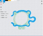
To shape the snap on bracket more sturdy, you could place a kind of elastic hinge, like in my draft below. This would lower the risk of material fracture when bending. The thickness of the hinge could be lower than the rest of the collar (unlike my sketch shows).
Attachments
Last edited:


")


