Because of the problems outlined by Kevin P above and an additional one that I found after the referenced discussion on magnification with Henry Link, one of the math of the magnification getting a little wonky as you approached, and passed, the front focal point of a lens system.
Those who wish to do FOV observations may want to consider using a collimating lens for these measurements. This method has the following advantages:
- Easier to set up than a linear distance arrangement.
- Optics are always tested at infinity focus, were they are designed.
- A bench test, takes a lot less space, typically about 300-400mm versus the shortest focus distance of the optic under test.
- Depending on the care setting up and the calibration procedure should be more accurate than the tape method because of the problems listed above.
- The setup can be made more permanent by erecting the setup in a wooden box or similar.
- The same setup can be used for rough evaluation of the optics, such as examining the grid for astigmatism, curvature, pincushion or barreling at infinity focus.
- Lighting and air currents along the test path are far easier to control due to the very short distances.
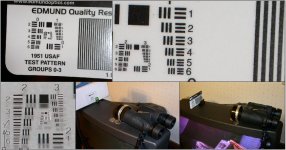
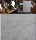
The attached pictures are of a 200mm lens with an Edmunds resolution card at focal point, one with the camera at 35mm focal length and the other at 280mm focal length. Note that by blowing the 280mm picture up you can see the maximum resolution of the card, group 3, element 6 which, at 200mm, is 14.3 lp/mm or 72.4 arc seconds and the ruled section is approximately 8.6 arc minutes per black or white line and 17.189 arc minutes per line pair. The other picture is the same setup but of a better resolution target and blows up to group 5, element 3 or 40.3 lp/mm or 25.6 arc seconds, not bad for a small aperture digital camera. The paper grid has replaced the resolution target and is spaced so the each grid square is 1 degree. The camera was different than the first on (this was a different setup than the first one so I could make a demo photo and took less time to set up than down load the pictures to the computer) and was only 100mm focal length and shows a horizontal FOV of about 19.1 degrees. This picture was just taken for demonstration purposes so I did not take any time in setting up, the camera was just hand held up to the collimating lens, hence the rotation and not quiet square to the target.
The two attached PDF’s grids are scaled to 3.49mm squares @ 200mm and 8.099mm squares @ 464mm. You can ratio the focal lengths to get to any focal length lens you may use. Be sure to print with “no scaling”.
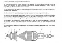
An infinity collimator is nothing more than a lens with a target at its focal point. This setup exhibits an interesting and useful property, that any parallel rays entering anywhere on the objective will hit a common spot on the target (reticle) or, conversely, a spot on the reticle will be projected out of the objective as parallel lines even if not parallel to the optical axis.
Lets make our first collimator. Real accuracy is not called for in these demonstrations since we are just going to discuss functions. We will talk about refinements in the future. First, plot the attached PDF, then take the paper grid and cut it out and tape it to the side of a box or bookend, the more perpendicular and flat, the better. Second, take the lens and set about 200 mm (or whatever focal length you may have available) away from the target. Third, take your finder (I find high powered, fixed focus finders handy just for this purpose), a binocular or telescope and focus on a star at infinity. Focus as best you can, generally the higher the power, the more accuracy that can be attained. Try not to disturb this setting. Place this instrument in front of the objective. Distance is not critical; a one to six inch distance is probably best. Do not touch the instrument focus but move the grid back and forth until the best overall focus is achieved. For future reference, note the distance from an identifiable point on the lens to the grid. This completes the collimator setup.
Lets make a few tests for function. First take your finder, a bino, camera or some other optic and place close to the objective. The grid should become in sharp focus at infinity setting. If the grid is properly positioned and the lens is actually 200 mm the grid spacing should be 1-degree increments with the sub marks along the center axis marked to 0.1 and 0.25 degrees. Check the FOV measurements against your published data. I have the luxury of having survey instruments available so I can directly measure the angles for a check.
If you are checking your finder with the cross hair, move it until you are just looking into the left edge of the lens and place the cross hair on the center of the grid. Note the angle of the finder. If you can slide the finder parallel, do so, otherwise move the finder to the look into the right side of the lens. When the finder is parallel to the first position, the cross hair will be on the center of the grid. You should be able to repeat this experiment at any single point on the grid.
Try it and let me know how it works out for you.
Sorry, could only attach 5 files, but you should still get the idea.
Kimmo;
I have not seen the Hawke or Zen yet but tested my Promaster by the method above late last year and came up with FOV’s of 7.43 degrees left tube and 7.6 degrees right tube.
Best to all.
Ron


 |.
|.