• Welcome to BirdForum, the internet's largest birding community with thousands of members from all over the world. The forums are dedicated to wild birds, birding, binoculars and equipment and all that goes with it.

    Please register for an account to take part in the discussions in the forum, post your pictures in the gallery and more.
ZEISS DTI thermal imaging cameras. For more discoveries at night, and during the day.

New Horizons II (1 Viewer)

Hello Jessie,

Thank you for your kind words. Feel free to write your own posts here. This thread is some sort of diary or log as I study and experiment with human vision and visual optical instruments. My time as a one-man-company is very limited so I can write here once or twice per week. I invite established forum members (e.g. elkcub, binastro, Gijs, John A Roberts, Holger, Troubador, WJC, Henry Link) to make their own contributions to this thread :)

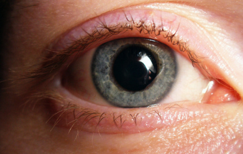
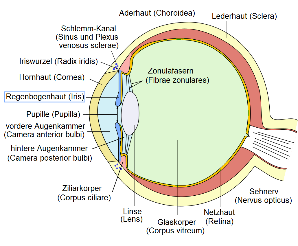
I have learned some significant facts about visual perception and telescope optics since I started this thread nearly two years ago: I didn't know about the accommodation reflex in the human eye and it's tendency to focus at an intermediate distance. I didn't know that afcocal telescopes form a virtual image at a very close distance to the eye when pointed at every day objects (which implies that the exit beam is not collimated and can have significant vergence). I didn't know that the primary function of the eye pupil is to control depth of focus (not brightness, that's a secondary function). I hadn't heard about the perceptual phenomenon known in psychology as "size constancy" so I re-discovered it myself (and mistakenly attributed it to out-of-focus blur) when I was testing a rifle-scope invention in October 2019 :geek:

A little suggestion to Omid, who invents: I would like to have a focus that is speed switchable. Minox already had something there, different mechanical transmission (focus speed) in the near and far range. I would like 2 speed levels manually selectable by me. My car has 6 automated gears in its transmission, "alpha bins" (or better high end binoculars) costs a lot and have complicated therefore fault prone focus system with combination of focus and dioptric compensation. Every cheap small car has manual selectable 4 forward gears and 1 reverse gear.

Regarding your desire for switchable speed focus, I am afraid it is not among my projects. Go ahead and design that yourself! But the issue that I have highlighted in your quote is on my mind. I agree that the focus mechanisms in recent binoculars have become exceedingly complex. I mentioned this in one of my previous posts in the forum. I am working on advanced concepts in which the need for focusing is completely eliminated. An early example of such binoculars is the Rollei 7X42 which is itself is a derivative of the British Army L12A1 binoculars from 1980s.


Best regards,
Omid
 
Last edited:
Omid, post 261,
Nice presentation of the Avimo/Rollei 7x42. Another nice description with photographs is also present on the WEB-site of Hans Leichtfrieds "Fernglasmuseum: .
And I have finished a couple of weeks ago an investigation of a number of 7x40/42 binoculars and among that also he Rollei (published on the WEB-site of House of Outdoor). Personally I was not impressd by the level of user comfort of this binocular and its optical properties, but that is a matter of taste.
Gijs van Ginkel
 
Any of this, of course, is perfectly open to query, discussion or disagreement, but you have chosen to spend your time attacking the OP and me for reasons that only you can understand.
In my last post especially I tried to make very clear what I objected to here: disjointed tidbits or teasing puzzles dispensed by Omid (which I find dubious or frustrating), as well as sheer repetition from you (which actually began in another thread, but would annoy me in any context). You just stonewall when challenged, Omid prefers not to respond at all, so no substantive discussion ensues. I don't understand why neither of you wants to engage in more direct or productive conversation, but since you both seem determined to ignore any such suggestions, I won't belabor the point further.
 
Last edited:
AW to post #261:
Hello Omid, thank you for your detailed answer. Each point I can not judge with my current expertise - but in subsequent things I have problems with my current knowledge. I must explain that I do not well understand complex technical texts in English language, which do not correspond to my professional field. Therefore I look for German writings to the discussed topic. Furthermore, it may well be that these points have already been discussed satisfactorily and that I have not read everything. Probably, therefore, simply links to a corresponding discussion or links to sources are sufficient to answer. Note: If I want to justify things that correspond to my knowledge, and the German Wikipedia writes the same, I simply take the German Wikipedia and let text parts translate automatically (DeepL). Let's start.
I didn't know that the primary function of the eye pupil is to control depth of focus (not brightness, that's a secondary function).
The width of pupils is adjusted according to the incidence of light by two smooth muscles in the iris. The pupil constrictor (Musculus sphincter pupillae) constricts the pupil, the pupil dilator (Musculus dilatator pupillae) dilates it. This adaptation process is unconsciously regulated. A high intensity of light incidence is transmitted to the brain via the optic nerve and can trigger pupil constriction (miosis) from the Edinger-Westphal nucleus via the parasympathetic part of the oculomotor nerve. At low light incidence, the pupil is made wider (mydriasis) because of the lower parasympathetic effect, and the maximum pupil width depends on the sympathetically innervated musculus dilatator pupillae. An increase in sympathetic tone (as in startle) can also lead to mydriasis by activating the dilatator pupillae muscle.
The retina, on which the image seen is formed, adapts only slowly to changes in the luminance of the environment. Therefore, the iris takes over the instant adjustment. Only after the immediate adjustment by the iris do the sensors of the retina get used to the changed luminance.
To differentiate: Luminance is a physical, objective and measurable unit. It is measured with the unit cd/m2. Brightness is the subjectively perceived quantity for the light received by the retina.

The iris attaches with its iris root to the ciliary body and leaves an opening in its center, the pupil. Its width is involuntarily regulated by the contraction of muscles: near the edge of the pupil, the ring-shaped, parasympathetically innervated sphincter pupillae muscle causes a narrowing of the visual aperture. The sympathetically innervated dilator pupillae muscle, which runs in a fan shape on the posterior side of the iris, dilates the pupil opening. Both cause pupillary dilation, the involuntary adaptation to different light conditions and regulate the amount of light entering the eye. The dilatation of the pupil is called mydriasis, the constriction is called miosis.
The iris as actuator adjusts the effective pupil width according to the luminance (light density). The change in depth of field is therefore a secondary effect.
I didn't know that afcocal telescopes form a virtual image at a very close distance to the eye when pointed at every day objects (which implies that the exit beam is not collimated and can have significant vergence).
A "virtual image" is known from simple ray optics. This is a thought model, which means a reasonable simplification of reality to explain or calculate some effects. If one model is not enough, one needs another, maybe even a more complex model. In short, ray optics is applicable to objects of observation, images and optical components much larger than the wavelength of light. Otherwise, the wave-particle duality of light is known - and thus other, finer, more complex models. Let us come to the virtual image. The virtual image (a thought model, it was intentionally virtual = not real, not existing in reality, but appearing real) has the following properties:
  • It is not projectable on a screen, photographic film or similar.
  • No (reflected) light emanates from it.
This model of thinking is used with mirrors, magnifying glasses and Kepler telescope. The reader should look for corresponding explanations in his native language. Our binoculars are now Kepler telescopes with a erection system (prisms), which "folds" the light path and thus shortens the build length. For the image formation, the erection system is irrelevant. In the following I refer therefore exclusively to the Kepler telescope, its real and virtual image.
The real image of a focused Kepler telescope lies in the focal plane of the objective and eyepiece. The eyepiece acts like a magnifying glass, it magnifies the real image. The thought model of a magnifying glass (thus with virtual image) with the observation object in the focal plane is applicable. At which place is the virtual image, which is only a mental model - not projectable?
The German Wikipedia has either an awkward way of expressing itself or a mistake in thinking:
Caption: Ray path in the Kepler telescope. The objective (1) produces an inverted, real intermediate image (5) of the object (4), which is viewed with the eyepiece (2). The eye (3) sees a magnified, virtual image (6) at an apparently short distance (dashed lines).
Now the explanation that is plausible for me:
Rays parallel to the axis are united by a converging lens into the focal point; parallel rays which are not parallel to the optical axis are not united into the focal point, but into the focal plane. So there (in the focal plane) the intermediate image is formed.
This real intermediate image is viewed through a second converging lens with a small focal length. This second converging lens is called eyepiece, through which this intermediate image is observed. The eyepiece acts like a magnifying glass, i.e. it magnifies the intermediate image accordingly. The result is a magnified, virtual image of the intermediate image - and thus an inverted, side-swapped virtual image of the object at a larger angle of view than that at which it would be seen without a telescope. (The image is not magnified compared to the original, of course).
Eyepiece and objective have as distance the sum of their two focal lengths, so the intermediate image is also in the focal plane of the eyepiece (the image-side focal plane of the objective is at the same time the object-side focal plane of the eyepiece).
Since the rays leave the eyepiece in parallel and parallel rays intersect only at infinity, the eye therefore sees the final image at infinity (indicated by the dashed lines in Figure 2).
I think the eyes focus for a very large distance because of the almost parallel rays when observing terrestrical objects (not infinitely but >> focal length). Kepler telecopes are afocal systems. The ray-optical model of thinking of the Kepler telescope as an afocal system imho does not explain the effect of focusing for observing objects at close range (observations with binoculars). For this purpose, we mentally disassemble the telescope into 2 parts: A magnifier (eyepiece) with the real intermediate image in the focal plane. The function becomes clear, if everyone looks for explanations in his native language for the illustration of magnifying glasses or collecting lenses with the observation object in the focal area.
The necessity and function of focusing becomes clear if one does the same for the imaging of the objective: It is again the imaging of a converging lens - but the object of observation is at a much greater distance than the single or 2x focal length. Thus the image formation of the real intermediate image takes place at different places between objective and eyepiece related to the optical axis - and in case of insufficient focusing just not in the focal plane of the eyepiece. A picture says more, see penultimate picture (section "Unterschiedliche Bilder an Sammellinsen").
Since it fits here, I would like to answer another question (PM) from a member: In many ray optic models, the eye lens is not explicitly named or drawn. However, the models take it into account, e.g. by a virtual image of mirrors, magnifiers, Kepler telescope. The simple ray-optical models for afocal systems do not:
The Kepler telescope as an afocal system requires a converging lens for image projection onto a screen, photo film or the retina. I have done an experiment: Place a candle, binoculars at a distance of about 2 m, focus, lie bins down and align it so that the candle is visible through an eyepiece. With a light cardboard behind the eyepiece, you never get a sharp image of the flame, the exit pupil appears dark. If you put a magnifying glass between cardboard and eyepiece and try different distances, you will get a bright, sharp, almost punctiform image of flame. Distances about: Magnifier (~4x) about 4 cm behind eyepiece, cardboard about 12 cm behind eyepiece.
A consequence: To check the resolution of binoculars with the eyes, you need another afocal system (booster, additional bins), a magnifier does not work. I am not an optic expert. Corrections are welcome. Jessie
 
Last edited:
Regarding your desire for switchable speed focus, I am afraid it is not among my projects. Go ahead and design that yourself! But the issue that I have highlighted in your quote is on my mind. I agree that the focus mechanisms in recent binoculars have become exceedingly complex. I mentioned this in one of my previous posts in the forum. I am working on advanced concepts in which the need for focusing is completely eliminated. An early example of such binoculars is the Rollei 7X42 which is itself is a derivative of the British Army L12A1 binoculars from 1980s.
I see the following possibilities here for an automatic focus with a control loop consisting of a measuring element, feedback controller and actuator, among other (optical) things:
  • (multi-field) distance measurement as in modern cameras
  • electronic feedback controller
Possibilities for the actuator:
  • mechanical displacement of objective lenses, eyepieces or a focusing lens (stepper or linear motor?)
  • electrically deformable lenses (principle like in older IS binoculars for deformation of prisms)
  • electrical change of the optical properties of the lens material (refraction index), lenses possibly filled with suitable liquids or gases
In any case, batteries or akkumulators are probably needed. Thus, I recognize an implementation acceptable to the customer, especially in IS binoculars. Possibly in future fully electronic binoculars with feedback controlled objective optics in the electronic camera and display with residual light amplification + (switchable) heat picture cams.

By the way, the Rollei 7x42 is a fixed focus binocular with a limited depth of field, you can't even focus with the individual eyepieces.
"However, the Avimo is an exception: The stars are fine at the center, but already less than 50% off they start deforming. This poor performance is of course a consequence of its fix-focus feature. It is not possible for me to find the optimized focus for my eyes, so that the full performance of this binocular remains inaccessible."
Best wishes. Jessie
 
Last edited:
Hi Jessie,

Thank you for taking time and writing such detailed posts! I am sure it has taken a significant amount of your time to look up each topic and then translate the German passages into English. So, I sincerely appreciate your interest and enthusiasm. Most of what you have written is factual and accurate but sometimes it is the small details that we need to pay attention to. Let's focus on just one topic (pupil size) and leave other topics for later.

The iris as actuator adjusts the effective pupil width according to the luminance (light density). The change in depth of field is therefore a secondary effect.

Your first sentence is obviously correct. We all know that the pupil dimeter changes by ambient luminance. But the sentence would become more accurate if we make it a bit longer as follows:

The iris as actuator adjusts the effective pupil width according to ambient luminance and the state of our eye's accommodation (lens focus) and the balancing action of our autonomic nervous system .

The last factor causes our pupil diameter to change
depending on the degree of our alertness. Similarly, our eye pupil will dilate if we notice an attractive woman in a cocktail party! :)

tom.jpg

Eye pupil dilation and constriction are not voluntary. The iris is unconsciously controlled via two feed-back loops:

The first feedback loop responds to ambient light. It is also interesting to note that the brain does not use the same photo receptors that form our visual perception (i.e. rod and cone receptors) to adjust the pupil. It seems that certain ganglion cells are used for this purpose.

The second feedback loop adjusts the eye pupil according to accommodation (focus) and convergence between the two eyes. When you look at a near object, three things happen together: your eye lens changes shape (accommodates), your pupil constricts and your two eyes converge. This coordinated reflex is known as Near Triad.

Restricting the iris aperture is really necessary for seeing close objects. You would appreciate the significance of this if you have done macro photography. Modern macro lenses - such as Nikon 105mm f/2.8 which I have - automatically prevent the photographer or the camera from setting the lens to maximum aperture if the distance is too close. Our brain does the exact same function.

The constriction of the eye pupil when we focus on a near object is clearly demonstrated in the video below:


The two neural pathways that contribute to the accommodation reflex and ambient light reflex are described in the video below:


The change in depth of field is therefore not a secondary effect or a mere side-effect of change in illumination. Our brain reduces the iris aperture intentionally and specifically to increase DOF when looking at near objects. A most amazing fact is that when we look at a near object, we never notice that our vision becomes darker despite the fact that our pupil constricts and less light enters the eye! :unsure: :)

-Omid
 
Last edited:
Omid, first of all, thank you. You are absolutely right that pupil/iris width is influenced by many more things than just luminance. Note: I have slightly changed my text on optics, nothing in principle, just a few better words. I don't see your pictures (?), there are big blanks in your post, probably my too strict adblocker prevents that. I must check it tomorrow. And now I'm going to bed. So long. Jessie

Edit:
Ah, the blackouts are Youtube videos. Okay, in post #265 I only translated excerpts from the documents regarding the influence of luminance. The documents also briefly describe some of the influences on pupil width that you described in detail. Thank you. I don't want to classify what is primary and what is secondary with my layman's mind, I don't have the medical knowledge, I just believe you. ;-)
I enjoyed the Tom and Jerry cartoons very much when I was young, thank you for reminding me of them! The cat in love. :)
With regard to my research-based statements on optical models of the Kepler telescope with derivations to binoculars (observations of terrestrial objects at non-infinite distances), I would like to add a link that Henry Link was kind enough to provide in another context:
I look forward to the further interesting discussion.
 
Last edited:
Post #267.

What about large dark sunglasses?

And if they are worn above the eyes?

Clever sellers watch the eyes.
If the pupils become dilated the price of the item viewed goes up.

Regards,
B.
 
Topic: Afocal Keplerian telescope operating at finite conjugate

Omid, first of all, thank you.

You are most welcome.

my research-based statements on optical models of the Kepler telescope...

Before you "research" further, please read post #201 in this thread and try to answer the question. Draw a diagram like the one I had attached on a piece of paper, then turn off your computer, pick up a pencil and solve the problem yourself. :)

Tip 1: Use the two-step method you explained in post #265: First, find the exact position of the real image formed by the objective lens. Then use this real image as an "object" for the eyepiece and find where the eyepiece forms the final virtual image.

Tip 2: Use the Newtonian form of lens equation: (image distance from back focal plane) x (object distance from front focal plane) = f x f

Tip 3: Assume that the tree distance is measured from the front focal plane of the objective. Calculate and report the distance (d) of the final virtual image with reference to the back focal plane of the eyepiece. This position is very close to the exit pupil where we put our eye in a telescope, so quite acceptable as a reference point to measure the virtual image distance from the eye.

After you finish your calculations and made sure that everything is correct, turn on your computer and compare your answer with my statement in post #205.

I look forward to the further interesting discussion.

OK, we'll do after you solve the problem on a piece of paper and post a picture of your results!! :)
 
Last edited:
Hi Omid,
Before you "research" further, please read post #201 in this thread and try to answer the question. Draw a diagram like the one I had attached on a piece of paper, then turn off your computer, pick up a pencil and solve the problem yourself. :)
I will try this with pencil, ruler and paper, probably on Monday. Again, back to the last topic, luminance control or depth of field as a primary or secondary effect.
The first feedback loop responds to ambient light. It is also interesting to note that the brain does not use the same photo receptors that form our visual perception (i.e. rod and cone receptors) to adjust the pupil. It seems that certain ganglion cells are used for this purpose.

The second feedback loop adjusts the eye pupil according to accommodation (focus) and convergence between the two eyes. When you look at a near object, three things happen together: your eye lens changes shape (accommodates), your pupil constricts and your two eyes converge. This coordinated reflex is known as Near Triad.
With 2 control loops, can one really say across the board which is primary and which is secondary? It is a multivariable control. Separate consideration of the control loops is hardly possible. A technical example would be a luxury greenhouse in which temperature and relative humidity are to be controlled (kept constant corresponding to 2 reference variables with several disturbance variables). Based on your example with macro photography at close range (small aperture desired), I can well imagine that both control loops you mentioned have different strong effects at far and close range or in different ambient light or, or. The evaluation of what is primary and what is secondary could be an dispute about Emperor's beard. Therefore, I accept now your statement without contradiction. I consider the totality of your information on both control circuits to be much more important. And you showed us, emotional influences are added to 2 control loops of pupil width. ;-)
Thank you for your effort and all the detailed information. So long.
Jessie
 
Last edited:
Hi Omid,

With 2 control loops, can one really say across the board which is primary and which is secondary?

I agree that it is a matter of opinion to say which of the two control loops is primary. Both functions are very important to our vision.

It is a multivariable control.

Yes, it is. I happen to know a little bit about feedback control systems because my doctoral advisor, Prof. Bruce A. Francis, was one of the world's most distinguished scientists in this field. You can see him in the picture below standing near the center (tall person with white hair). The picture was taken in 2014 in Los Angeles where Prof. Francis delivered the plenary lecture at the IEEE Conference on Decision and Control (CDC) and was awarded the Hendrik W. Bode Prize for his contributions to control theory. Shortly after, in 2015, Professor Francis also received the Control Systems Award, the highest honour in the field of control bestowed by the IEEE.

I am standing on the far right of the picture wearing suit and tie. Next to me is Prof. Hideaki Ishii from Tokyo Institute of Technology, Japan, and next to him is Prof. Togwen Chen from University of Alberta, Canada. Tongwen and Hideaki were students of Prof. Francis as well. They are now distinguished professors themselves. Hideaki and I completed our degrees nearly at the same time (2002).

The 2014 award ceremony in Los Angeles was last time I saw Prof. Francis. He passed away in March 2018. I am probably the only person among his doctoral students who did not become a university professor. I hope Bruce forgives me for that while he rests in eternal peace.

-Omid


Bode_Prize_Picture_Small.jpg
 
Last edited:
Hi Omid/Jessie,

I've been meaning to mention that if you don't already have Sheldon Ebenholtz' 2001 book "Oculomotor Systems and Performance" in your library it would be a worthwhile purchase.

Ed
 

Attachments

  • Oculomotor Systems and Perception.JPG
    Oculomotor Systems and Perception.JPG
    455.3 KB · Views: 6
  • IMG_2379.JPG
    IMG_2379.JPG
    361.5 KB · Views: 6
  • Vergence in darkness.jpg
    Vergence in darkness.jpg
    85.5 KB · Views: 5
Last edited:
Virtual image, version 01: The homework of a lazy schoolgirl

Omid's task: At what distance do we see the virtual image of binoculars?
Distance of the observation object: d = 100 m
Height of the observation object: h = 10 m
Magnification of the telescope/binoculars: 10x

Like apparently many people, I make the simple popular assumptions:
1. the angle of view of the virtual image fom observation object is equal to the apparent angle of view from bins (real angle of view alpha * magnification m)
2. the height of virtual image h' is the height of observation object h multiplied with magnification (m) of the telescope: h' = m * h


With a sketch and some trigonometry, we get the equations:
tan (alpha) = h / d
tan (m * alpha) = m * h / d'
general school knowledge: tan (alpha) = 1 / arctan (alpha)

Transforming the equations and inserting them into each other, we get:
d' = m * h * arctan (m * arctan (h / d))
Result of the task: d' ~ 78.4 m

Did Omid miscalculate in post #205?
Or are the popular assumptions in common written above wrong? For this we consider the plausibility of the equations and result formula with limit values:
m = 1 as well as d --> infinity (for very large distances); 2 different tests for validity
This is my homework for interested readers. The result shows whether the popular assumptions in common are valid for virtual images. Do I need to do my homework again? Have fun thinking about it.
Jessie

Tip for pocket calculators: Use RAD (radiant) not DEG (degree). arctan also tan-1 ;-)
 
Last edited:
Jessie,

You did not follow my instructions! Instead of calculating what a Keplerian telescope does, you made two "popular assumptions"! (Of the two assumptions you made, only the first one is correct. You'll learn why the second assumption is wrong once you do the homework.)

OK, I'll give you one more chance: Do it again in two steps: First calculate the position of the real image formed by the objective:


Objective.jpg

Then calculate the position of the virtual image formed by the eyepiece:

Eyepiece.jpg

So, all I want you to do is to find Z2 prime given Z1 when the eyepiece lens is positioned behind the objective as in a Keplerian telescope.

Use the hints I gave you before in post #270.

Good luck! :)
 
Last edited:
You did not follow my instructions! Instead of calculating who a Keplerian telescope forms an image, you just made two assumptions and calculated how a "bigger image" can be made! Of the two assumptions you made, only the first one is correct.
Hi Omid, that is what I wanted to show. ;-)
But thanks for more solution hints, which I will now look at and read. I will still do correct homework. :)
I also studied feedback controller technology for a few semesters. A long time ago. I never needed it professionally. Too bad, it was a favorite subject during my studies. This field was a hobby, not my major. The top of it was multivariable controllers and adaptive controllers that automatically adapt to changes of controlled system. Lots of math in the frequency domain (Fourier analysis for signals and Laplace transform for systems). I still remember 2 simple calculation and adjustment methods for single-variable controls, named after their developers: methods according to Ziegler-Nichols and method Reinisch for analog controllers (P, PI, PID feedback controller). Do you also know this simple methods? PID controllers were also reproduced digitally. Which adjustment methods do you remember?

Theoretical modeling of systems with practical experiments (determination of system response with test functions such as noise, step/jump function, impulse or harmonic functions with frequency change, sweep, with spectrum analyzer or oszillograph) was highly interesting and this can also be applied to biological, societal, economic and social things. Social systems are arguably higher order systems, simplistically modeled PT2 systems. When there is an abrupt change in a command variable, overshoot often occurs until a steady state is reached. Many natural and engineered systems are PT1 systems with an e-function in response to step input signals, e.g. living rooms that are heated. Or low passes and high passes of the first order. With correct calculated and adjusted feedback control often PT2 systems are created in approximation. The impulse response of systems corresponds to the system transfer function in the time domain. By means of Laplace transformation one can calculate simply with multiplications in the frequency domain, no complex mathematical convolution in time area is needed. For computers, the Digital Fourier Transformation (DFT) and Fast Fourier Transformation (FFT) algorithms for signal analysis exist. Computers can calculate so fast that one can also use mathematical convolutions in the time domain. Gijs van Ginkel investigates light transmission function in spectral (frequency or wavelength) domain for binoculars. Modulation transfer function (MTF) is also a system response to "frequency changes" (changes of distance and width of black and white stripes).
I don't know if the abbreviations for analog linear feedback controllers (P, PI, PID) and analog linear systems (P, PT1, PT2 etc) are used in English, I was looking for a link with examples of different system responses but can only find German websites. Maybe someone can add an example English link for other readers?

Beautiful photo you have posted. Now I know who my teacher is. I also saw a picture of Gijs van Ginkel in his paper. Pretty laugh and full beard, that's what I remember. You look very serious.
So long and thanks for the interesting thread and conversation. And for my homework. Reminds me of seminars in my student days. Now I am retired and can deal with many interesting things. Your thread is one of them. Calculating correctly with false assumptions and checking plausibility with limit values was fun for me and I wanted to show readers something with it: Plausibility and validity of assumptions and statements, oversimplifications and generalizations is obviously checked far too little in everyday life. Looking at limit values is often helpful.
Jessie
 
Last edited:
Omid, post #275, Fig. 5
Virtual image of the eyepiece, questions
(The construction of the real intermediate image of the eyepiece is not a problem. The focal length is not necessary, the consideration of the focal length ratio (magnification) is sufficient for an overall result. It is only about the eyepiece and focusing.)


Omid's task: at what distance do we see the virtual image of binoculars? (Without specification of the exact focus.)
Distance of the observation object: d = 100 m
Height of the observation object: h = 10 m
Magnification of the telescope/binoculars: 10x
Omid's "multiple choice" solutions: post #203
Omid's solution: post #205: c- d=1m, h=1m (The image is moved 100X closer and shrinks 10X, providing an apparent magnification of 10X)

For the drawing construction of the virtual image of a telescope (eyepiece) the following information is needed: How was the binocular or Kepler telescope focused for the observation object, i.e. where exactly is the real intermediate image produced by the objective located with respect to the focal length or focal plane of the eyepiece?

Option A (better infinite options / solution set, therefore specification in task required):
Within the focal length of the eyepiece, the eye must accommodate < infinity. The location (distance) of the virtual image of the eyepiece depends on the exact location of the real intermediate image of the objective.

Option B:
The real intermediate image of the objective is exactly in the focal plane of the eyepiece. This is the "ideal" viewing distance (*) with a magnifying glass, the eye focused at infinity. The exit rays from the eyepiece in the direction of the eye run parallel, the virtual image is located at infinity, therefore a drawing construction is not possible, the image of an afocal optical system (parallel rays) is created. An astronomical telescope is adjusted in this way, i.e. the real intermediate image is located in the common focal plane of objective and eyepiece.

Exact specifications for option A appear to me as "academic arbitrariness" without practical relevance, so to say occupational therapy. The solution of Omid presented in post #205 is too little, a solution set, a mathematical function depends on the exact focusing is the solution.

Option B results approximately in an afocal system (**): https://de.wikipedia.org/wiki/Afokales_Linsensystem#/media/Datei:Kepler-Fernrohr_(scheme).svg
Due to the "ideal viewing distance" (relaxed eye focused to infinity), I consider this at the moment the only reasonable focusing of a Kepler telescope or binoculars even when observing terrestrial objects.

(*) This says my German physics book: Schneider, Zimmer: Physik für Ingenieure (university textbook, 1991)
as well as Dr. rer. nat. Wiebke Salzmann
"Mode of action of the magnifying glass
If the object is within the simple focal length, one obtains a magnified, upright, laterally correct, virtual image (in front of the lens, i.e. on the object side). Behind the lens, the rays do not intersect, only the imaginary extensions on the front side of the lens intersect - that is where the virtual image is created. If the object moves into the focal plane, the rays become parallels and the virtual image is created at infinity, where it can be viewed with a relaxed eye (see Figure 7).
gray dots = focal length, black dots = double focal length; gray arrows = object, black arrows = image"

as well as
"The object must be within the focal length to see it magnified by the loupe. Optimally, the magnifier is held when it is at the focal point. The rays then run parallel. The object appears to be infinitely far away and the eye can relax to accommodate at long distance."
Here the question arises whether really all users of binoculars / Kepler telescopes focus in such a way that the virtual image is created at infinity - or whether some do not focus on the distance of the virtual image at a smaller resting focus (probably very individual), so that the virtual image becomes constructible with corresponding measured values at finite distance."


A very simple "experiment": Everyone knows a reading magnifier. A magnified sharp page-correct virtual image is created at a very variable distance (0 to focal length) to a book, a newspaper. Now we use the same magnifier as a detail magnifier, about the way watchmakers do with "clamping" magnifiers in their eye sockets - or how an eyepiece is used: Reading magnifier at a short distance (about 2 ... 3 cm with my 5x magnifier) in front of the eyes and thus look at one of your fingers: You have to observe in a much smaller variable range (near the focal point) for a sharp image. I think, I focus thereby on infinity, light rays run parallel, the virtual image is in the infinity and is therefore not constructible. It is a virtual image because it appears on the object side to the eye. Just as mirror images. Whether my eyes really focus to infinite, I can't say for sure, in any case my finger is close to the focal point of magnifier with very little possible variation of my finger for a sharp image - in contrast to the normal use of a reading magnifier with object or lens shifting possible within the entire focal length and with a constructible virtual image at finite distance.

(**) The observation of terrestrial objects in non-infinite distance leads to an objective image (= real intermediate image), which is not in the focal plane of the objective and also shifts with changes of the observation distance. See image formation of converging lenses with object width > focal length. This results in the need for variable focusing.
See also Fig.4 in post #275.

Summary:
Omid's task without specifying the exact focusing does not give a unique solution but a infinite solution set, a mathematical function in limited interval of eyepiece focal length. I think for most observers, according to my physics book and several websites, the binoculars or telescope is adjusted so that even with terrestrial observation the real intermediate image of objective is focussed/shifted in the focal plane of the eyepiece and thus no drawing construction of the virtual image at infinity with 2 of the 3 distinguished/special/excellent light rays for simple ray optics is possible. I consider Omid's unique solution and problem definition with 4 multiple choices to be wrong (at least incomplete), already because this does not consider the possible solution set. A discussion for differently "popular" or "right" places of the virtual image (infinity, rest focus distance etc.) I do not consider meaningful because of the individuality of the observers regarding to the special task considered here. One observer may focus the virtual image (just a simple model of simple ray optics, no objective reality) to infinity, the other to rest focus, the third between, short and long sighted people, spectacle weares? No light emanates from the virtual image, it is not projectable, it is a simple but reasonable thought model. However, the exact focusing of objective and eyepiece for individual observers and special observation objects in measurable observation distances could be determined, e.g. with X-ray picture of the individual focused binoculars and known or mesured focal lengths of objective and eyepiece.
This is my current knowledge, my current conclusions, errors in thinking are possible. I am not an optics expert. So long. Jessie
 
Last edited:
Keplerian telescope operating at finite conjugate - Part III

I consider Omid's unique solution and problem definition with 4 multiple choices to be wrong (at least incomplete), already because this does not consider the possible solution set. A discussion for differently "popular" or "right" places of the virtual image (infinity, rest focus distance etc.) I do not consider meaningful because of the individuality of the observers regarding to the special task considered here. One observer may focus the virtual image (just a simple model of simple ray optics, no objective reality) to infinity, the other to rest focus, the third between, short and long sighted people, spectacle weares?

Jessie,

Thank you again for taking considerable time and thinking around the problem I posed. :unsure::D The problem I asked you to solve is extremely simple if one thinks clearly but it can get extremely confusing if one doesn't. Don't blame yourself for finding the problem so confusing. I was in a state similar to you two years ago.

OK, back to our basic problem: I had tasked you with the specific problem of calculating the image position in an "afocal Keplerian telescope" when the object is at a finite distance. (Read the title of Post #270 and the second sentence in post #201.) The term afocal has a precise technical meaning: it means the objective lens and the eyepiece lens are positioned such that the eyepiece focal plane and the objective focal plane coincide. There is no focusing in such an optical system.

Here is a very clear diagram with assumptions and pertinent laws of optics included. The objective lens L1 forms a real image of the owl at a small distance "p" behind its focal plane F. The eyepiece lens L2 takes this image as its object and forms a "virtual image" of the owl. We want to find the "position" of this virtual image.

I hope you and other readers can solve the problem now. It should take less than 2 minutes to find the solution.

Best regards,
-Omid


PS. With this post, I will take an extended vacation from Birdforum and leave it to other knowledgeable members to continue and expand on various topics presented in this thread. It has been a mostly enjoyable experience yet very time consuming and energy-draining as well. I have decided to stop writing here and focus instead on my professional work. Thank you all for following my discussions with interest! :)


Telescope_Diagram.jpg
 

Attachments

  • Telescope_Diagram.pdf
    187.2 KB · Views: 3
Last edited:
The term "afocal" has a very specific meaning: this means the objective lens and the eyepice lens are positioned such that the eyepice focal plane and the objective focal plane coincide.
versus post #275 Fig. 4 (objective image for terrestrial objects in non-infinite distances)?!

and
Fig. 5 (eyepiece image formation) is wrong: The real intermediate image of objective is in focal plane of eyepiece (simple magnifier function of eyepieces). The virtual image is therefore not constructable, it is in infinite distance, excellent optical rays direction eye are parallel.

Many optical formulas originated from simple ray optics by means of trigonometry. We must first agree on a picture of ray optics model. You draw with 2 from 3 of the excellent rays, I can't. I gave lengthy reasons for this. ;-)
Jessie

Addendum:
Just tried: When I lengthen a tube of my binoculars with the diopter compensation, the close-up distance of this tube shortens (single-eye observation). I'll think about what this means in our discussion tomorrow. I am tired now. Good night for Omid and all other readers.
 
Last edited:
I now solve Omid's task according to post #201:
The virtual image is always created at infinity (and is therefore not constructible), since in any case the exit rays of the eyepiece are parallel - assuming that an user focuses the telescope so that eye accommodates to infinity. According to my researched and repeatedly linked literature, this is the case.

The constructions are based on an imaginary decomposition of the telescope into a converging lens (object distance > 2x focal length) and a magnifying glass (real intermediate image of the objective always in the focal plane of the eyepiece). The constructions explain vividly the necessity and function of focusing as a simple change of the distance between objective and eyepiece. The focusing is necessary because the real intermediate image of the objective shifts according to the distance of the observation object.
kepler-irdisch-v02.jpg
Further conclusion:
1. Only in astronomical use (focus infinite) is the Kepler telescope an afocal system. The fact that the focal planes of the objective and eyepiece are superimposed is only a technical consequence of the necessary focusing. There are other afocal systems than the infinite focused Kepler telescope, e.g. telecentric objectives. According to the German Wikipedia, the definition of an afocal system is:
"An afocal system is a lens system that neither collects nor disperses light. This means that rays arriving in parallel are refracted convergently or divergently within the system, but further lenses or mirrors in the optical path cause the light to emerge again in a parallel direction. In other words, light rays arriving parallel to the optical axis also leaves the system parallel to the axis."
2. It should be examined to what extent formulas for the astronomical Kepler telescope also apply to terrestrially focused binoculars, provide exact results or approximate values.

Evaluation of:
When I lengthen a tube of my binoculars with the diopter compensation, the close-up distance of this tube shortens (single-eye observation). I'll think about what this means in our discussion tomorrow.
1. The ray-optical image formation constructions correspond exactly to my observation: The distance between objective and eyepiece must be increased for the close-up range.
2. Wether my eyes focus to infinity when observing at close range of about 2 m I cannot assess. It is remarkable that after closing my eyes for a short time (about 30 seconds) and then observing the object at a distance of 2 m, the accommodation of my eyes with binoculars is clearly faster than without binoculars: With binoculars I see a sharp image noticeably earlier. I'm an older person with low akkomodation and reading glasses.
 
Last edited:
Warning! This thread is more than 3 years ago old.
It's likely that no further discussion is required, in which case we recommend starting a new thread. If however you feel your response is required you can still do so.

Users who are viewing this thread

Back
Top