• Welcome to BirdForum, the internet's largest birding community with thousands of members from all over the world. The forums are dedicated to wild birds, birding, binoculars and equipment and all that goes with it.

    Please register for an account to take part in the discussions in the forum, post your pictures in the gallery and more.
ZEISS DTI thermal imaging cameras. For more discoveries at night, and during the day.

25-50x: Improving the eyecup for eyeglasses wearers (1 Viewer)

Swissboy

Sempach, Switzerland
Supporter
Switzerland
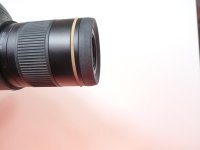
This concerns Swarovski's well known zoom eyepiece 25-50x. Despite it's wide FOV, for many wearers of eyeglasses, there is a considerable loss of FOV if one needs the glasses while using the scope. In my case, I quickly realized that I could only get the full FOV if I removed the eyecup. However, that would quickly lead to scratches on the eyeglasses. Thus, I tried to find a way to reduce the distance to the lens with a modification of the eyecup. The result, and a before-and-after comparison have already been presented in another thread:
http://www.birdforum.net/showthread.php?t=238276 in posts #12 and 13.

Here, I'd like to explain what we did.

First, however, I need to thank my son Claudio for his help. While he is not a professional on the lathe, he sure proved to be a very precise worker on it.
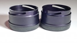
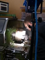
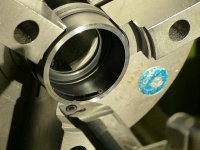
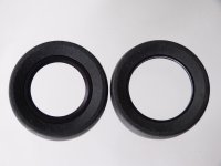
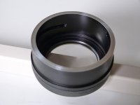
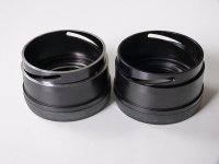
So here, first, are two pictures of the work in progress. I should emphasize, however, that one could get this done by anybody who knows how to operate a lathe. It was pure coincidence that my son said he could do it himself.

The second picture already reveals the three areas (blank rings) we worked on.
 

Attachments

  • P1070830red.jpg
    P1070830red.jpg
    143.5 KB · Views: 343
  • P1070828red.jpg
    P1070828red.jpg
    146.6 KB · Views: 337
Last edited:
Here are the two pictures shown together as a pdf in the other thread. First the original Swarovski configuration, then the modified version. At first sight, the two version look rather similar. However, the wide blank looking ring around the lens in the modified version corresponds to the narrow blank ring in the original. Thus, we essentially removed the inner part of the eyecup to allow to screw it in more.
 

Attachments

  • P1070908red.jpg
    P1070908red.jpg
    98 KB · Views: 307
  • P1070909red.jpg
    P1070909red.jpg
    94.9 KB · Views: 315
The widened central opening of the eyecup can be seen in these pictures. One of the final touches was to open the very top by just a little bit. That's the narrow blank ring visible here. All the rest was done from the inside with the eyecup attached to the lathe as seen in the first post.
 

Attachments

  • P1070917red.jpg
    P1070917red.jpg
    94.9 KB · Views: 248
  • P1070922red.jpg
    P1070922red.jpg
    75.8 KB · Views: 251
....All the rest was done from the inside with the eyecup attached to the lathe as seen in the first post.

There are three areas we worked on. These are visible as blank rings in the left one of the attached pictures.

First: opening the center without damaging the thread that is needed to attach the eyecup to the eyepiece. The eyepiece has a thread outside of the metal cone that holds the top lens. It is well visible in the second picture. This thread is used to hold the eyecup. And the opening of the modified eyecup needs to go over that thread.

Second: the corresponding thread on the eyecup is on a kind of protruding collar on the inside of the eyecup. We took off just a bit less than two millimeters of that collar to allow for screwing the eyecup down further. In order to make sure that we would not damage the thread, we made the fine adjustment of the opening only after having tried the eyecup on the eyepiece. That fine adjustment was made from the outside as mentioned in the previous post. With our modification, there are still around two millimeters of thread left which is sufficient to secure the eyecup on the eyepiece. The remaining thread can be seen, albeit a bit out of focus, between the innermost two blank rings.
 

Attachments

  • P1070919red.jpg
    P1070919red.jpg
    67 KB · Views: 250
  • P1070650redret.jpg
    P1070650redret.jpg
    91.1 KB · Views: 227
Last edited:
There are three areas we worked on. ........

The theoretical maximum reduction of the distance would be the gap seen between the eyepiece and the eyecup. Marked with a rubber band on the second picture. However, making complete use of this potential would first of all entail the complete removal of the internal thread on the eyecup. As a result, the eyecup would no longer be fixed directly. Another solution would then have to be found to solve that problem.

The second problem comes from the fact that there is not that much room inside the outermost shell of the eyepiece to allow for pushing or screwing in the eyecup all that far.

This brings me to the last area we had done work on:

As can be seen in the left hand picture of the previous post, we also tried to remove some material from the outermost part of the eyecup. That part actually consists of two layers. These are used for the extension mechanism to allow non eyeglass wearers optimal use.
 

Attachments

  • P1070651redret.jpg
    P1070651redret.jpg
    88.8 KB · Views: 244
  • P1070655red.jpg
    P1070655red.jpg
    80.4 KB · Views: 223
Last edited:
......... That part actually consists of two layers. These are used for the extension mechanism to allow non eyeglass wearers optimal use.

The picture here shows the extended eyecups. As is obvious, there is a guide mechanism which involves a slot in the inner layer. And there is very little material that can be removed as long as one wants to still be able to use the extension. We tried to be on the conservative side for our first attempt. As can be seen when the two eyecups are compared. But this now means that we interfere with the zoom mechanism when screwing the modified piece in as far as possible. The zoom ring turns inside and is then rubbing against the blank area of the eyecup. We'll try to remove a bit more and see how it goes.

I'm still somewhat undecided whether I should simply forego the extension mechanism. It would be nice to still have it, but as I'm by far the main and mostly the only user, it would not be a major problem. Even more so since I have an intact original eyecup as well.

At this point, I try to just very slightly unscrew the eyecup. But even that little bit already affects the comfort of having a full FOV. This also shows how critical even a tiny fraction of a millimeter is in this case. One would have wished for Swarovski to have paid more attention to this problem. It would certainly have been possible without too much of a sacrifice say in the extension mechanism.
 

Attachments

  • P1070910redret.jpg
    P1070910redret.jpg
    101.9 KB · Views: 230
Last edited:
That's very interesting...:cat:

I wear glasses and i find that positioning my eye can be quite critical at times to get a full FOV with the 25-50 zoom...

Perhaps i can get my mate to make me one of your adaptations...[or maybe you could sell me one]?...;)

All the best...!

http://username-beast.blogspot.co.uk/
 
........Perhaps i can get my mate to make me one of your adaptations...[or maybe you could sell me one]?...;)

All the best...!

http://username-beast.blogspot.co.uk/

The one I have was made after work at my son's work place. But he certainly can't start a business with this. I originally intended to have this made at some shop that has a lathe. But I would first have had to search for one.

The reason I tried to be as specific as possible was to provide instructions for some local provider you or anybody else who is interested will hopefully find. It took my son about an hour to do it, but much of that was searching for equipment, like a strong light and the appropriate measuring tools. A more experienced operator in a decently equipped shop should be able to do this in less than 30 minutes, I think.
 
Last edited:
Finally got it perfect

.....interfere with the zoom mechanism when screwing the modified piece in as far as possible. The zoom ring turns inside and is then rubbing against the blank area of the eyecup. We'll try to remove a bit more ..........

It took a while before we (my son Claudio and I) both found time to finish this venture. But it's done now. Taking off another 0.5 mm still kept the extension mechanism fully functional. Yet, the zoom ring is now moving freely.

The pictures show how the situation looks now, always with an original next to the modified eyecup. As one can see, there is really not much more to remove now before actually affecting the extension mechanism. Maybe we now took off a little bit more than absolutely necessary.

Once again, my thanks go to Swarovski and my scope supplier Atelier Rieter (http://www.das-fernglashaus.de/Swarovski1.htm) for providing an extra eyecup, and thus making it easier to try this experiment. And special thanks to my son for doing such a fine job. B :)B :)B :)
 

Attachments

  • P1100170red.jpg
    P1100170red.jpg
    93.1 KB · Views: 251
  • P1100171red.jpg
    P1100171red.jpg
    63.7 KB · Views: 268
  • P1100176red.jpg
    P1100176red.jpg
    106.1 KB · Views: 246
A brief follow-up

......The pictures show how the situation looks now, always with an original next to the modified eyecup. As one can see, there is really not much more to remove now before actually affecting the extension mechanism. .......Once again, my thanks go to Swarovski and my scope supplier Atelier Rieter (http://www.das-fernglashaus.de/Swarovski1.htm) for providing an extra eyecup, and thus making it easier to try this experiment. And special thanks to my son for doing such a fine job. B :)B :)B :)

Having used the scope with the described modifications for 8 months now, I can only say that this was a good decision to venture into the eyecup alteration. The scope has served its purpose splendidly without any negative effects coming from the modification. And I get the desired large FOV which I could not get before.
 
WOW, what a story!! :t:

Reminds me of the story my father told of someone who sent the thinnest wire they could make to the Swiss watch institute, and challenged them to do better. The institute send it back with a hole drilled down the center.

Ed
 
Swissboy

Bit late on this topic but thank you for taking the time to post this. I have a high prescription +4.75 and this caused me to find that zoom was a no go on comfort viewing. I was pleased to note that the new ATX has a special eyecup with a 4mm reduction in height over the standard eyecup that allows the eye to get a lot nicer view although the standard one was acceptable.

I bought the DCBII for the new setup only to find you have to replace that eyecup for another "standard" version with a special lip around!

Swarovski were great and although they say they have no plans to address this they did halp me out with a spare eyecup in case of butchering this one.

In short I would like to ask how you got the rubber eyecup off the metal cylinder without damage as I note there is a glue all around the inside of the recessed slot of the eyecup.

Again thanks for the post.
 
Swissboy

I was pleased to note that the new ATX has a special eyecup with a 4mm reduction in height over the standard eyecup that allows the eye to get a lot nicer view although the standard one was acceptable.

I bought the DCBII for the new setup only to find you have to replace that eyecup for another "standard" version with a special lip around!

I noted the same thing, the issue with the digiscoping adapter is a bit annoying,

the low-rimmed ATX eye cup is definitely a help for me and without it, the old ATS gives me as good eye relief as the ATX,

Swissboy:

well done! amazing craftsmanship!

I wonder why swaro didn't construct a better eyecup from the beginning,
or at least give us a low-rimmed alternative as for the ATX.
 
Warning! This thread is more than 10 years ago old.
It's likely that no further discussion is required, in which case we recommend starting a new thread. If however you feel your response is required you can still do so.

Users who are viewing this thread

Back
Top